
Turn article assumptions into a first actuator family, model class, and evidence request.
Open catalog RFQ
2026/11/02
Quasi-Direct Drive (QDD) vs. High-Ratio Geared Actuators for Humanoids: Sourcing & Sizing Guide
Compare QDD vs high-ratio humanoid actuators by inertia, backdrivability and thermal duty. Use the sizing example and RFQ checklist to shortlist joint modules.
Quick answer: In a quasi-direct drive (QDD) vs. high-ratio geared actuator comparison for humanoid robots, shortlist QDD when low reflected inertia, backdrivability, and current-based force estimation dominate. Shortlist high-ratio strain wave or precision cycloidal modules when compact packaging and motor torque reduction during sustained loading dominate. Either family needs model-specific thermal and overload checks. Joint location alone does not determine the winner; a hybrid allocation is a design option, not a universal industry standard.
Published and reviewed: November 2, 2026. Scope: Global engineering and procurement evaluation for electromechanical humanoid robot rotary actuator modules. This is a source-based selection framework with explicitly hypothetical sizing calculations. We have not performed comparative hardware endurance tests or collected current supplier quotations. Research-platform results and manufacturer specifications apply to the cited designs, not every actuator of the same topology. Validate your joint trajectory, impact loads, cooling, and driver limits before design freeze. Linear actuators and their linkage geometry require a separate analysis.
For engineering directors, mechatronics leads, and procurement teams, the objective is to compare candidates against the same joint duty and acceptance criteria. Review our QDD Humanoid Actuators, Highly Integrated Rotary Modules, High-Torque Leg Actuator Modules, and Force Control Actuator Selection. These are sourcing categories; request the exact motor, reducer, and driver configuration with each quotation.
1. The Architectural Dilemma: Reflected Inertia vs. Continuous Torque
Electric motors typically run faster than humanoid joints. Reduction trades motor speed for output torque, but also changes the inertia and friction seen at the joint output.
For an ideal rigid, single-axis transmission, use:
J_ref,out = J_rotor × N² + J_gear,outHere N = motor speed / output speed, and both inertia terms are expressed at the output in kg·m². This excludes limb inertia and transmission elasticity. The rotor contribution grows with the square of ratio for a fixed rotor inertia; different motor designs must be compared using their actual inertia.
- Quasi-Direct Drive (QDD): A low-ratio transmission, often single-stage planetary, paired with a relatively high-torque motor. For this guide's screening examples,
N = 5–12, so the rotor multiplier is25–144. Low friction and low total reflected inertia can improve passive backdrivability. - High-Ratio Geared Actuators: Strain wave or precision cycloidal reducers provide larger reductions. For this guide's examples,
N = 50–160, giving a rotor multiplier of2,500–25,600. A smaller rotor can offset part of this increase. High ratio does not itself establish self-locking or an impact rating.
Two useful starting points are dynamic contact control, where low mechanical impedance matters, and sustained payload support, where motor heating and packaging matter. The Mini Cheetah platform paper demonstrates a particular low-ratio actuator implementation on a quadruped; it does not establish the architecture of commercial humanoids or a universal joint allocation rule.
2. Mechanical Transmission Dynamics & Backdrivability
Compare starting friction, running friction, efficiency, and control bandwidth at the same output load, speed, and temperature.
2.1 Quasi-Direct Drive Mechanics
A common QDD arrangement uses a sun gear, planets, an output carrier, and a fixed ring gear. A single planetary stage still contains sun–planet and planet–ring meshes; its efficiency is not a fixed family-wide percentage.
For slow reverse motion, a simplified drag balance is:
T_backdrive,out ≈ N × T_drag,motor / η_reverse + T_drag,gear,outT_drag,motor is motor-side drag and T_drag,gear,out is additional gear drag referred to the output. Define losses consistently to avoid counting gear friction twice. Starting friction, seals, cogging, brake state, and grease temperature require measurement; this approximation excludes rotor acceleration and is not a static self-locking test. Low ratio can reduce reflected motor drag, but does not guarantee easy manual motion.
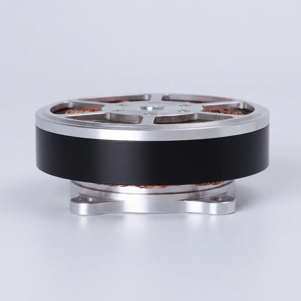
Motor packaging illustration. The photo does not show an assembled planetary stage or verify actuator torque, ratio, or impact capability.
2.2 High-Ratio Geared Actuator Mechanics
As detailed in our Strain Wave vs. Cycloidal Reducers Guide, strain wave gears use a flexible toothed member, while cycloidal reducers use eccentric discs and pin contacts. Their friction and stiffness characteristics differ, even at the same ratio.
- Efficiency: Request a load–speed–temperature map rather than assigning one efficiency to a topology. Running efficiency cannot directly predict zero-speed holding losses.
- Backdrivability: A high ratio can increase reflected drag and inertia, but an unpowered joint is not necessarily locked. Gravity holding requires a separately specified brake or other validated mechanism.
- Torsional compliance: Strain wave reducers can have load-dependent stiffness and hysteresis. Ask for the named model's stiffness curve and lost-motion definition. Zero nominal backlash does not mean zero deflection or positioning error.
3. Impact Dynamics, Shock Absorption & Proprioception
Foot-contact loads depend on contact stiffness, effective mass, posture, velocity, and impact duration. Acceleration in g alone cannot determine a joint's overload torque; use a joint-space load model and an instrumented acceptance test.
3.1 Shock Absorption & The Impact Mitigation Factor (IMF)
Wensing et al. (2017) introduce the Impact Mitigation Factor (IMF) in a legged-robot model to compare backdrivability at impact. Applying that metric to a humanoid requires its model assumptions and configuration; a rotor multiplier alone is not an IMF or a gear survival prediction.
- In a QDD system, lower reflected inertia can allow more joint motion during contact. Motor acceleration, structural compliance, friction, and electrical braking all influence the response. Regeneration needs a bus that can accept or dissipate energy; capacitors alone do not guarantee safe bus voltage.
- In a high-ratio system, increased reflected inertia can raise mechanical impedance. Overload may damage the transmission, but failure is not inevitable: peak torque limits, pulse duration, bearing loads, and compliance govern acceptance. Planetary gears also have overload and fatigue limits.
The diagram shows a conceptual comparison, not measured stress or a passed drop test. Its N² labels multiply each candidate's own rotor inertia; they do not compare complete actuator inertia.
3.2 Proprioceptive Force Sensing vs. Dedicated Torque Cells
A useful moving-operation estimate is T_out ≈ N × K_t × I_q × η, with a consistent torque-constant/current convention. It estimates transmitted motor torque, not external contact torque directly. Rotor acceleration, friction, gravity, and limb dynamics must be accounted for before inferring contact forces.
- In QDD actuators, lower friction and reflected inertia can make current-based estimation practical. Calibrate against a reference transducer over temperature, speed, and load; specify allowable bias, error, and bandwidth.
- In high-ratio actuators, stiction and hysteresis can make estimation harder. Consider a dedicated output torque sensor, a calibrated elastic element, or dual encoders with a validated stiffness model. Encoder difference alone is not a torque measurement.
Neither architecture automatically removes the need for independent sensing in a safety-related function. Current-loop sampling frequency is not measured force-control bandwidth.
4. The Thermal Reality & Static Holding Penalty (I²R Losses)
QDD can require more motor torque for the same joint load. Whether it runs hotter depends on motor constants, winding resistance, cooling, and the actual duty cycle.
4.1 Motor Sizing Fundamentals (D²L Scaling)
At comparable magnetic flux density B and linear current loading A, a useful torque scaling is T ∝ B × A × D² × L, where D is air-gap diameter and L is active stack length. A larger diameter can increase torque capability while also changing rotor inertia and packaging. It does not establish a universal motor diameter for either topology.
4.2 Resistive Heating in Static Stance: A Reproducible Example
At zero speed, mechanical output power is zero (P_mech = T × ω), while energized windings still generate heat. The MIT Cheetah energy-efficiency study explains why actuator heat and transmission losses belong in system-level selection.
Hypothetical calculation, not hardware test data: Compare two different motors holding 60 N·m at the output. Assume balanced sinusoidal phase currents, no brake assistance, and neglect static gear friction. K_t,rms is motor torque per phase RMS ampere; R_phase is phase-to-neutral resistance at the assumed operating temperature. Do not substitute a line-to-line resistance or a peak-current torque constant without conversion.
T_motor = T_joint / N
I_phase,rms = T_motor / K_t,rms
P_cu = 3 × I_phase,rms² × R_phase| Input or calculated result | Illustrative QDD candidate | Illustrative high-ratio candidate |
|---|---|---|
| Output holding torque | 60 N·m | 60 N·m |
| Reduction ratio N | 8 | 100 |
| Assumed K_t,rms | 0.30 N·m/A RMS | 0.12 N·m/A RMS |
| Assumed R_phase | 0.030 Ω | 0.200 Ω |
| Required motor torque | 7.50 N·m | 0.60 N·m |
| Calculated phase RMS current | 25.0 A | 5.0 A |
| Calculated copper heat | 56.25 W | 15.0 W |
| Assumed rotor inertia | 0.000200 kg·m² | 0.000015 kg·m² |
| Rotor inertia referred to output, excluding gears | 0.0128 kg·m² | 0.1500 kg·m² |
The first heat result is 3 × 25² × 0.030 = 56.25 W; the second is 3 × 5² × 0.200 = 15 W. In these assumed candidates, lower holding heat trades against higher reflected rotor inertia. These values establish neither continuous torque ratings nor winding temperatures. Use thermal resistance, thermal capacitance, ambient temperature, mounting, and a heat-run test to establish allowable holding time. There is no universal time to overheating.
The 1/N² copper-loss relationship holds only with fixed motor constants and resistance in this idealized torque balance. Changing the motor changes the comparison. For moving duty, also check motor speed (ω_motor = N × ω_out), acceleration torque, back-EMF, efficiency, and driver voltage headroom. At 5 rad/s output, these ratios require 40 and 500 rad/s motor speed respectively; neither candidate is approved without its torque–speed curve.
5. Comprehensive Actuator Architecture Comparison
This is a screening framework, not a table of guaranteed market specifications. Ratio bands are working examples rather than standardized topology boundaries; every numerical requirement belongs in the model-specific RFQ.
| Evaluation metric | Quasi-Direct Drive (QDD) | High-ratio geared (strain wave / cycloidal) | Mid-ratio planetary |
|---|---|---|---|
| Reduction ratio used in this guide | 5–12 | 50–160 | 15–35 |
| Gearbox technology | Often single-stage planetary | Strain wave or precision cycloidal | Often multi-stage planetary |
| Motor packaging | Relatively high-torque motor; check diameter | Reduced motor torque demand; check maximum speed | Balance motor envelope and transmission stages |
| Rotor inertia multiplier N² | 25–144 | 2,500–25,600 | 225–1,225 |
| Mechanical backdrivability | Often a design priority; measure output drag | Strongly model-dependent; no automatic self-lock | Measure starting and running drag |
| Impact acceptance | Low inertia can help; verify gear and bearing overload | Verify overload pulse, fatigue, and compliance | Verify gears, pins, bearings, and overload pulse |
| Current-based force estimation | Calibrate friction and inertial compensation | Account for hysteresis and load-dependent stiffness | Validate compensation over temperature |
| Continuous torque density | Compare whole-module mass and identical cooling | Compare whole-module mass and identical cooling | Use the same duty and cooling conditions |
| Static holding heat | Compute from actual K_t, resistance, and current | Can reduce motor torque; still needs thermal checks | Depends on selected motor and ratio |
| Inverter requirement | Check phase current and regeneration capacity | Check phase current and electrical speed | Check both current and speed limits |
| Backlash / lost motion | Measure across load and reversals | Distinguish nominal backlash, hysteresis, and elastic deflection | Specify loaded reversal test |
| Sourcing cost | Quote complete module and driver together | Include reducer, feedback, brake, and qualification | Include stages, bearing support, and integration |
| Joint allocation | Candidate where contact response dominates | Candidate where packaging and sustained torque dominate | Candidate where mixed constraints dominate |
6. Humanoid Anatomical Joint Allocation Matrix
Use the following as an editorial starting shortlist for an adult-size humanoid, not a claim about any manufacturer's deployed design. Posture, payload, gait, linkage geometry, and cooling can reverse a recommendation. A fall can load any joint; the table's load cases are examples, not a safety classification.
| Anatomical joint | Example dominant load case | Starting architecture shortlist | Qualification question |
|---|---|---|---|
| Hip pitch | Leg swing and ground contact | QDD or mid-ratio planetary | Does measured output impedance meet contact-control needs within thermal limits? |
| Hip roll | Single-leg support and lateral recovery | QDD, mid-ratio, or high-ratio | Can it sustain the stance torque while meeting lateral recovery bandwidth? |
| Hip yaw | Steering and pelvis rotation | Mid-ratio planetary or QDD | Do speed, drag, and packaging meet the trajectory? |
| Knee | Squatting, propulsion, and landing | QDD or another qualified rotary module | Do peak duration, bearings, and holding heat pass the same load cycle? |
| Ankle pitch | Push-off and uneven ground | QDD or a compliant high-ratio arrangement | What are output overload and contact response under the chosen linkage? |
| Ankle roll | Lateral leveling and edge contact | QDD or another low-impedance arrangement | Does the complete joint backdrive with the brake released? |
| Torso / waist pitch | Upper-body gravitational moment | High-ratio or thermally qualified lower-ratio | Can the system hold payload and arrest motion on power loss? |
| Shoulder pitch / roll | Tool positioning and payload support | High-ratio or QDD with adequate cooling | Do mass, force estimation, and sustained duty meet requirements? |
| Elbow & wrist | Distal mass and precision orientation | Compact high-ratio, planetary, or tendon | Do lost motion, cable routing, and distal inertia meet the task? |
Review High-Torque Leg Actuator Modules and Compact Arm and Wrist Actuators using these same acceptance questions.
7. Commercial Sourcing Economics & Supply Chain Realities
7.1 Actuator Module Sourcing Economics
No current supplier quote dataset supports a universal QDD price advantage. A planetary reducer may simplify some manufacturing steps, while a larger motor, driver, cooling system, or bearing arrangement can offset that saving. Compare delivered systems at the same continuous duty and lifetime target, not just equal peak torque labels.
For each prototype, pilot, and volume tier, request an itemized quote covering motor, reducer, output bearings, driver, encoders, brake, harness, cooling interface, tooling/NRE, and qualification tests. State currency, quote date and validity, Incoterm, taxes/duties, warranty, and exclusions. Include expected scrap, field replacement, and requalification cost in the decision.
7.2 Lead Times and Vendor Concentration
Treat lead time as a dated supplier commitment, not a topology property. Ask separately for sample availability, custom tooling, pilot approval, production capacity, and shipping. Verify whether a second source has equivalent mounting, feedback, firmware, and test evidence; matching ratio or outer diameter does not make modules interchangeable.
8. Engineering & Procurement RFQ Specification Checklist
Before design freeze, give suppliers the same joint load spectrum and enforce this 10-point checklist. Numerical examples below are proposed request conditions, not product ratings.
- 1. Reflected inertia & ratio: Obtain motor rotor inertia and gear inertia with their reference shafts stated. Compare total
J_ref,out = J_rotor × N² + J_gear,outagainst the joint acceleration budget. - 2. Continuous vs. peak torque: Request continuous stall and moving-duty curves at your ambient and mounting conditions, plus peak duration, repetition rate, and cool-down requirement. Separate repeated peaks from emergency overload.
- 3. Driver alignment: Declare DC bus voltage, phase RMS and instantaneous peak current limits, current-duration limits, and the torque-constant convention. Check motor electrical speed, voltage headroom, and regenerative energy handling.
- 4. Backdrive torque: Request starting and running output drag at defined speeds, temperatures, brake states, and powered/unpowered driver states.
- 5. Dynamic impact: Specify output torque pulses, rise time, duration, repetitions, and bearing loads. Record acceleration sensor location separately; g is not a substitute for output torque. Define post-event inspection and rejection criteria.
- 6. Thermal path & sensing: Obtain winding-to-housing and housing-to-ambient thermal data, time constants, mounting assumptions, and sensor placement. Define winding, magnet, bearing, and electronics limits with a heat-run test.
- 7. Feedback architecture: Specify required output accuracy and torque-estimation error, then select motor/output encoders and any torque transducer. Distinguish encoder interfaces such as BiSS-C or SSI from module communication such as CAN FD or EtherCAT.
- 8. Mechanical packaging: Confirm diameter, length, whole-module mass, output-bearing load ratings, flange tolerances, and usable cable bore. Check the actual harness through the full joint range.
- 9. Holding brake & E-stop: Define gravity load, stopping strategy, brake holding torque, engagement/release times, and power-loss behavior. A static holding brake is not automatically rated for dynamic emergency stopping.
- 10. Quality & lifetime: Agree end-of-line drag, noise, lost-motion, and runout criteria; define load-cycle endurance, sample count, lubrication, allowed wear, and failure criteria. Record configuration and traceability for each accepted sample.
9. Frequently Asked Questions (FAQ)
Can a humanoid robot use QDD actuators for all joints?
Yes, if motor size, current, cooling, and holding duty meet every joint's requirements. That does not make an all-QDD design universally efficient or inefficient. Compare the full trajectory and power-loss holding strategy; the hypothetical 60 N·m example illustrates one trade-off, not a complete humanoid energy budget.
Why can high-ratio harmonic gearboxes fail when a humanoid falls?
An overload can exceed tooth engagement, flexspline fatigue, or bearing limits. Reflected inertia affects the transient, but a fall does not guarantee failure. The Harmonic Drive gear catalogue discusses stiffness and ratcheting; request the exact model's permissible overload and post-event inspection rules. QDD gearsets also require impact qualification.
Does QDD eliminate the need for joint torque sensors?
No. Current-based torque estimation can be useful after calibration and dynamic compensation, but suitability depends on required accuracy, bandwidth, temperature range, and fault coverage. Use a dedicated sensor when those requirements cannot be demonstrated with estimation.
What is the maximum practical gear ratio for a QDD actuator?
There is no universal cutoff. This guide uses 5–12 as a screening band. Assess actual rotor inertia, drag, motor torque constant, and measured force response rather than approving a design because its ratio falls below a label threshold.
How do inverter requirements differ between QDD and high-ratio actuators?
At the same output torque, a lower ratio requires more motor torque; phase current also depends on the selected motor's K_t. A higher ratio increases motor speed at the same output speed. Check phase current, bus voltage, electrical frequency, thermal duration, and regeneration together. DC supply current and motor phase current are different quantities.
Can software compliance replace the physical impact protection of QDD?
Control can shape contact response within its measured bandwidth and actuator limits. It cannot establish gear survival for an untested impact. Mechanical compliance, rotor inertia, sensor latency, current limits, and contact stiffness interact; qualify the complete joint under representative transients.
10. Summary and Next Steps
Start with QDD candidates when low output impedance is the main constraint. Start with high-ratio candidates when packaging and sustained motor torque dominate. Compare both against identical trajectories, cooling conditions, feedback requirements, and overload acceptance tests before selecting a hybrid or single-family architecture.
Engineering & Sourcing Actions
- Evaluate standard QDD modules: Request torque–speed curves, motor constants, and measured drag through our QDD Humanoid Actuators Catalog.
- Review high-ratio integrated joints: Confirm the named reducer, brake, and feedback configuration in Highly Integrated Rotary Modules.
- Compare lower-limb candidates: Check continuous duty and abnormal-event evidence for High-Torque Leg Actuator Modules.
- Submit your joint load spectrum: Send torque/speed versus time, payload, bus limits, cooling, quantity, and required delivery date through our Engineering RFQ Contact to request candidate documentation and a sample quotation.
Sources & References
Sources support the stated physical principles or named designs. They do not validate current market prices, delivery dates, this guide's hypothetical motors, or any supplier's humanoid module. Review the comparison when a candidate's motor, reducer, cooling, or duty requirements change.
- Wensing, P. M., et al. (2017) — Proprioceptive Actuator Design in the MIT Cheetah: Impact Mitigation and High-Bandwidth Physical Interaction for Dynamic Legged Robots. IEEE Transactions on Robotics, 33(3), 509–522. DOI:
10.1109/TRO.2016.2640183. Research on proprioceptive actuation and the model-dependent impact mitigation factor; not a universal gearbox shock guarantee. - Katz, B., Di Carlo, J., & Kim, S. (2019) — Mini Cheetah: A Platform for Pushing the Limits of Dynamic Quadruped Control. ICRA, 6295–6301. DOI:
10.1109/ICRA.2019.8793865. A specific modular, low-ratio quadruped implementation, not a survey of commercial humanoid joints. - Harmonic Drive SE — Harmonic Drive Gears: Engineering Data. Manufacturer catalogue, document
1053522; consult the engineering-data sections on torsional stiffness and ratcheting. Values and limits depend on the named series and operating conditions. - Seok, S., et al. (2015) — Design Principles for Energy-Efficient Legged Locomotion and Implementation on the MIT Cheetah Robot. IEEE/ASME Transactions on Mechatronics, 20(3), 1117–1129. DOI:
10.1109/TMECH.2014.2339013. Author manuscript in MIT's repository covering actuator heating, transmission losses, and energy-efficient drivetrain design.
Author

Categories
Buyer path
After Reading
Use the guide to choose the next sourcing action.
Convert the guide into application-risk notes before asking for samples or controlled files.
Send prototype contextCarry accepted article checklists into sample release, pilot supply, and OEM documentation control.
Prepare OEM sample plan1. The Architectural Dilemma: Reflected Inertia vs. Continuous Torque2. Mechanical Transmission Dynamics & Backdrivability2.1 Quasi-Direct Drive Mechanics2.2 High-Ratio Geared Actuator Mechanics3. Impact Dynamics, Shock Absorption & Proprioception3.1 Shock Absorption & The Impact Mitigation Factor (IMF)3.2 Proprioceptive Force Sensing vs. Dedicated Torque Cells4. The Thermal Reality & Static Holding Penalty (I²R Losses)4.1 Motor Sizing Fundamentals (D²L Scaling)4.2 Resistive Heating in Static Stance: A Reproducible Example5. Comprehensive Actuator Architecture Comparison6. Humanoid Anatomical Joint Allocation Matrix7. Commercial Sourcing Economics & Supply Chain Realities7.1 Actuator Module Sourcing Economics7.2 Lead Times and Vendor Concentration8. Engineering & Procurement RFQ Specification Checklist9. Frequently Asked Questions (FAQ)Can a humanoid robot use QDD actuators for all joints?Why can high-ratio harmonic gearboxes fail when a humanoid falls?Does QDD eliminate the need for joint torque sensors?What is the maximum practical gear ratio for a QDD actuator?How do inverter requirements differ between QDD and high-ratio actuators?Can software compliance replace the physical impact protection of QDD?10. Summary and Next StepsEngineering & Sourcing ActionsSources & References
More Posts
Engineering NotesProcurement Guides
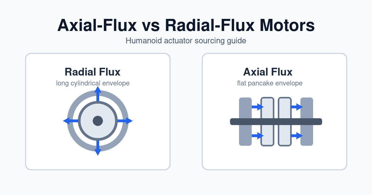
Axial-Flux vs. Radial-Flux Motors for Humanoid Actuators: A 2026 Sourcing Guide
Compare axial-flux vs radial-flux motors for humanoid actuators in 2026: torque density, thermal limits, tooling cost, joint fit, and RFQ sourcing checks.

Engineering NotesProcurement Guides
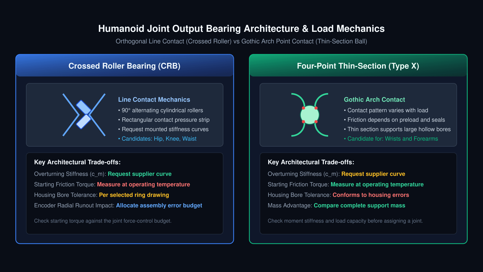
Crossed Roller Bearings vs. Four-Point Contact Thin-Section Bearings in Humanoid Robot Actuators: Sourcing Moment Rigidity, Preload Classes, and Runout Tolerances
Compare crossed roller and four-point thin-section bearings for humanoid actuators. Review moment stiffness, preload, runout, and RFQ qualification checklist.
Engineering NotesProcurement Guides
Strain Wave vs. Cycloidal Reducers for Humanoid Rotary Actuators: A 2026 Sourcing & Engineering Guide
Compare strain wave vs. cycloidal reducers for humanoid rotary actuators. Check shock ratings, lost motion, sizing examples, and prepare your supplier RFQ.