
Peak torque
- Typical Range
- Joint and robot-mass dependent
- Why It Matters
- Leg joints see short overload events that can be much higher than steady walking torque.
High-torque humanoid leg actuator modules for hip, knee, and ankle joints where load capacity, impact tolerance, braking, and thermal repeatability matter.
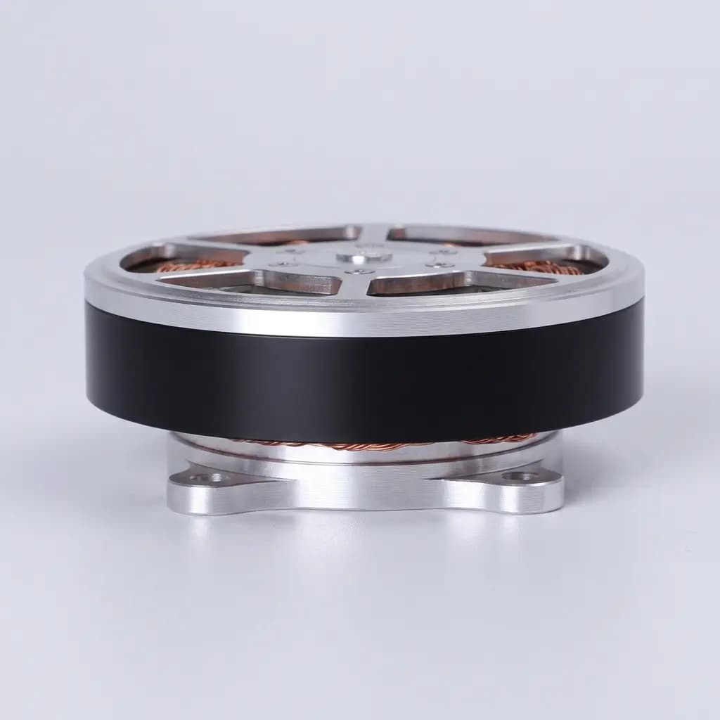
Reference visual for selection context. Confirm controlled drawings, CAD path, and test records for shortlisted models.
Engineering Asset Status
Current site images are reference selection visuals for catalog navigation. They should not be treated as final factory photos, CAD drawings, test records, or lot-specific inspection documents. For shortlisted models, request the controlled packet tied to model code, drawing revision, test condition, and sample lot.
Reference visuals, product-family routes, RFQ class matrices, and validation checklists for early selection.
Controlled datasheet, drawing or CAD path, torque-speed or thermal record, wiring notes, and sample or OQC evidence.
Verified factory-floor photos, teardown images, and lot-specific test reports are not presented as public evidence until real project assets exist.
| Metric | Typical Range | Why It Matters |
|---|---|---|
| Peak torque | Joint and robot-mass dependent | Leg joints see short overload events that can be much higher than steady walking torque. |
| Continuous torque | Thermal-path and current-limit dependent | Humanoid gait tests can fail when a motor is selected from peak torque only. |
| Output stiffness | Reducer and bearing architecture dependent | Hip and knee joints need predictable positioning under load and impact. |
Use these representative classes as shortlist anchors. Final quoted samples depend on confirmed drawings, torque-speed duty cycle, thermal assumptions, protocol, brake, encoder, and validation requirements.
Mid-load knee and ankle rotary class
Integrated reducer rotary module
Knee-light, ankle pitch/roll, waist, shoulder-heavy
18-45 Nm continuous
80-150 Nm peak
20-80 rpm output class
OD 70-90 mm / reinforced output bearing
48-60 V DC
Dual encoder preferred
Shortlist after robot mass and duty cycle
Thermal rise, overload duration, backlash, brake behavior, and shock load.
Heavy hip actuator class
High-torque integrated rotary module
Hip pitch/roll/yaw, heavy knee, impact test rig
60-120 Nm continuous
220-450 Nm peak
10-45 rpm output class
OD 95-140 mm / high moment-load support
48-72 V DC
Dual encoder plus torque feedback option
Engineering review before sample release
Continuous torque envelope, housing heat path, impact load, and bearing support.
110 mm high-torque frameless class
Frameless torque motor
Knee, hip-light, shoulder-heavy, low-ratio reducer input
10-30 Nm continuous
50-120 Nm peak
KV and thermal-path dependent
OD 100-125 mm / large ID option
48-60 V DC
Absolute encoder or dual feedback
DFM and thermal assumption review
Continuous torque, heat rejection, rotor inertia, and reducer coupling.
| Class | Form / Joint Fit | Output Window | Interface Assumptions | Sample Gate |
|---|---|---|---|---|
HRA-R70-KNEE Mid-load knee and ankle rotary class 50-150 Nm class | Integrated reducer rotary module Knee-light, ankle pitch/roll, waist, shoulder-heavy | 18-45 Nm continuous 80-150 Nm peak 20-80 rpm output class | OD 70-90 mm / reinforced output bearing 48-60 V DC Dual encoder preferred | Shortlist after robot mass and duty cycle: Thermal rise, overload duration, backlash, brake behavior, and shock load. |
HRA-R95-HIP Heavy hip actuator class >150 Nm class | High-torque integrated rotary module Hip pitch/roll/yaw, heavy knee, impact test rig | 60-120 Nm continuous 220-450 Nm peak 10-45 rpm output class | OD 95-140 mm / high moment-load support 48-72 V DC Dual encoder plus torque feedback option | Engineering review before sample release: Continuous torque envelope, housing heat path, impact load, and bearing support. |
HRA-FTM110-O 110 mm high-torque frameless class 50-150 Nm class | Frameless torque motor Knee, hip-light, shoulder-heavy, low-ratio reducer input | 10-30 Nm continuous 50-120 Nm peak KV and thermal-path dependent | OD 100-125 mm / large ID option 48-60 V DC Absolute encoder or dual feedback | DFM and thermal assumption review: Continuous torque, heat rejection, rotor inertia, and reducer coupling. |
Evidence Before Sample PO
This product family should be evaluated with practical evidence before a first sample PO. The goal is to confirm fit, duty, control interface, validation target, and repeatability without pretending that every controlled drawing or test record is a public download.
Approve leg actuator samples only when duty cycle, thermal path, brake behavior, and joint mounting are clear.
Do not place a sample PO from peak torque alone when robot mass, gait cycle, and heat path are unknown.
| Gate | Buyer Input | Supplier Evidence | Hold Signal | No-Go Signal |
|---|---|---|---|---|
| 01. Fit baseline | Joint position, robot class, available OD / length / bore, mounting interface, cable exit, and first quantity. | Candidate model family, envelope drawing, accessory boundary, and whether a standard model or OEM interface is required. | At least one model path can be mapped to the mechanical envelope without inventing unconfirmed dimensions. | The inquiry only says "humanoid actuator" or "high torque motor" without joint, envelope, or quantity context. |
| 02. Duty and thermal check | Continuous output, peak output, peak duration, speed or stroke, cycle profile, current limit, and ambient assumption. | Rated versus peak boundary, torque-speed or force-stroke explanation, temperature-rise note, and current-limit assumption. | Selection is based on continuous duty and validation cycle, not peak output alone. | The sample decision depends on a peak rating while repeated gait, lift, grip, or force-control cycles are undefined. |
| 03. Interface and control check | Voltage bus, protocol, controller location, encoder, brake, pinout, cable length, and firmware integration boundary. | Wiring / protocol note, controller compatibility, brake / encoder assumption, and connector or harness options. | Electrical and control interfaces are clear enough for a bench test without late adapter redesign. | Mechanical fit is accepted but protocol, feedback, brake, or harness integration is still ambiguous. |
| 04. Sample validation check | The specific pass / fail test for the first sample: backlash, thermal rise, noise, force response, impact, or stroke repeatability. | Focused inspection note, test record type, revision baseline, and which result should be checked by the buyer after receipt. | Both sides know what evidence will decide whether the sample can move toward pilot planning. | The sample PO is placed without a named acceptance check or revision trace. |
| 05. Pilot continuity check | Pilot quantity, repeat-order forecast, inspection expectation, packaging / shipping limits, Incoterm, and destination. | Repeat-lot change-control path, outgoing inspection scope, packaging baseline, and commercial delivery assumption. | The accepted sample can be repeated without silent model, drawing, accessory, or firmware drift. | The project treats a one-off sample as proof of supply readiness without defining repeat-order controls. |
Curves and Structure Evidence
Public pages can introduce the actuator family, but final sample approval should be based on the records behind the rating. Use this checklist to ask for performance envelopes, duty assumptions, and section-view evidence without treating unverified marketing numbers as engineering proof.
| Evidence | Buyer Question | Input to Provide | Supplier Record | Decision Signal |
|---|---|---|---|---|
| Torque-speed or force-speed envelope | Does the actuator stay inside the usable output window at the target joint speed, not only at stall or no-load speed? | Target continuous output, peak output, required speed or stroke rate, bus voltage, and controller current limit. | Torque-speed, force-speed, or model summary with rated and short-duration peak boundaries stated separately. | Move forward only when continuous output, peak duration, and speed are judged together for the sample duty. |
| Thermal rise and duty-cycle basis | Will repeated gait, lift, grip, or force-control cycles push the motor, reducer, driver, or housing into thermal saturation? | Cycle profile, ambient assumption, cooling path, enclosure condition, duty ratio, and allowable surface or winding temperature. | Temperature-rise note, duty-cycle assumption, thermal path explanation, or sample test record tied to the selected class. | Treat peak torque claims as incomplete until the repeated-duty thermal boundary is clear. |
| Overload duration and recovery limit | How long can the module tolerate impact, squat recovery, step correction, or grasp overload before derating is required? | Expected overload multiple, duration, frequency, robot mass or payload, and pass / fail recovery behavior. | Peak duration note, overload inspection basis, brake behavior, bearing support comment, or derating boundary. | Use this as a hold gate for hip, knee, ankle, and force-control samples where impact or overload is material. |
| Control response and feedback loop basis | Can the motor, encoder, driver, brake, and protocol support the intended torque, position, or impedance-control behavior? | Control mode, update rate expectation, protocol, encoder requirement, current limit, brake behavior, and bench-test setup. | Controller compatibility note, encoder and brake assumption, wiring / protocol record, or matched kit recommendation. | Do not separate mechanical sample approval from control-stack compatibility. |
| Evidence | Inspect For | Input to Provide | Supplier Record | Boundary |
|---|---|---|---|---|
| Envelope drawing and CAD revision | OD, ID, axial length, flange, mounting bolt circle, output plane, cable exit, connector sweep, and assembly clearance. | Robot joint envelope, CAD revision, mounting constraint, cable direction, and any forbidden volume. | 2D envelope, controlled CAD path, drawing revision note, and interface boundary for the candidate class. | Public pages can show selection context; precise CAD should stay controlled until the model and project stage are clear. |
| Internal stack or section-view review | Motor, reducer, encoder, brake, bearing support, hollow routing, sealing surface, and structural heat path. | Target joint, load path, shock expectation, harness route, brake need, and feedback architecture. | Exploded-view reference, section-view note, component boundary, or engineering review comment for the selected sample path. | Use this to identify integration risks without implying that every supplier drawing can be published openly. |
| Backlash, stiffness, and bearing support basis | Reducer type, output bearing support, moment-load path, backlash target, compliance behavior, and repeatability risk. | Joint position, expected moment load, precision need, force-control target, and test that will decide sample acceptance. | Backlash record, stiffness note, bearing support statement, or application-specific inspection scope. | Especially important for leg modules, hollow-shaft modules, and compact arm joints where package size hides mechanical risk. |
| Harness, connector, and serviceability path | Cable bend radius, connector orientation, pinout, strain relief, service loop, and whether the joint can be assembled repeatedly. | Cable bundle, connector preference, controller location, service access limit, and repeat-order accessory expectation. | Wiring / protocol note, pinout baseline, harness option, accessory revision, or OEM interface recommendation. | A sample that fits mechanically can still fail the project if harness and connector assumptions are late. |
Treat this page as the selection context for datasheets, drawings, CAD access, wiring notes, and sample records. Controlled files should be requested with a candidate model, integration stage, and revision baseline.
| Packet | Best Timing | Documents | Input to Include | Boundary |
|---|---|---|---|---|
| Public selection packet | Early shortlist | Datasheet, model summary, basic envelope image, and application fit notes. | Target joint, output window, voltage / protocol assumption, and quantity direction. | Used for selection only; it is not a controlled drawing or final project guarantee. |
| RFQ-qualified engineering packet | Before sample quote | 2D envelope, interface notes, wiring / protocol note, accessory list, and sample gate. | Drawing revision, mechanical envelope, controller stack, and validation priority. | Provided after the model path is clear; it may still exclude editable CAD or supplier-controlled internals. |
| NDA-controlled CAD packet | Before mechanical freeze | STEP / CAD path, pinout details, revision-controlled drawings, and customization notes. | Confirmed candidate model, buyer entity, project scope, and NDA path if needed. | Not an automatic website download; controlled files depend on model, OEM scope, and permission. |
| Sample validation packet | Before pilot decision | Inspection note, focused test result, revision record, and packing / shipment baseline. | Accepted sample scope, test fixture context, pass / fail priority, and pilot quantity. | Generic records may not answer the application risk; request the exact test that matters. |
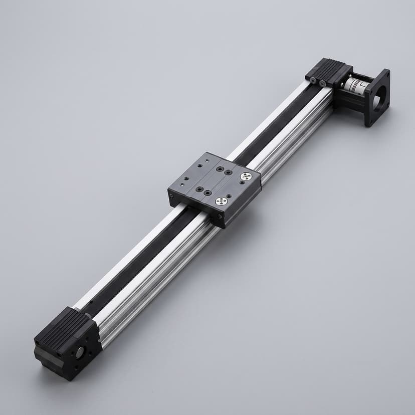
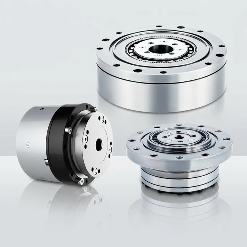
They can be used as baseline hardware for prototype testing once torque, speed, mounting, thermal, and control requirements are verified.
Yes. 48 V DC is a common humanoid robotics bus voltage, and we can compare 24 V, 48 V, and 60 V options by duty cycle and driver availability.
Procurement guide
Use the procurement guide when this product family is entering comparison, RFQ, or sample review. It translates page-level claims into torque-speed, interface, evidence, and supplier-readiness questions.
A buyer-side guide for pre-modular humanoid actuator sourcing: selection risk, evidence requests, sample readiness, and pilot supply controls.
Next sourcing step
01 Catalog shortlist
After a product family is shortlisted, validate the joint load case, sample gate, and evidence boundary before custom files or pilot timing enter the discussion.
Inquiry Email
Subject: RFQ Inquiry - High-Torque Leg Actuator Modules
This inquiry started from a product family page. Keep the request anchored to model-family fit, interface assumptions, and sample evidence. Source context: High-Torque Leg Actuator Modules.
Instant Chat
+8618857971991
Best for quick model-fit questions before a full RFQ email.