
Turn article assumptions into a first actuator family, model class, and evidence request.
Open catalog RFQ
2026/11/05
Dual Absolute Encoders vs. Single-Encoder Joint Modules for Humanoids: Sourcing, Deflection Sensing, and Functional Safety
Compare dual absolute encoders vs single-encoder humanoid joints. Assess deflection, startup position, safety evidence and BOM trade-offs with an RFQ checklist.
Dual absolute encoders vs single-encoder joint modules: choose motor-side plus output-side feedback when you need to observe transmission deflection or directly measure the limb angle at startup. A motor-side encoder alone can suit a joint whose position-error budget tolerates transmission effects. Two encoders do not, by themselves, establish torque accuracy, safe stopping, or a functional safety Performance Level.
For humanoid engineering and procurement teams, the key question is which errors must be observable at the joint output. A high-resolution motor encoder cannot directly measure gearbox windup, coupling slip, or output-side lost motion. An output encoder adds that measurement, together with mounting, calibration, communication, and validation work. Neither sensor sees structural bending beyond its mounting location.
This guide compares those trade-offs and provides questions for a supplier RFQ. Start by comparing the feedback configurations available through Actuator Controller & Encoder Kits and Highly Integrated Rotary Modules; ask for the exact sensor locations rather than relying on the phrase “dual encoder.”
Sourcing Scope, Method, and Verification Limits
Editorial review date: November 5, 2026.
Audience and region: Global, English-language guidance for mechatronics engineers, hardware architects, procurement leads, and integrators sourcing humanoid rotary joints.
Scope: BLDC or permanent magnet synchronous motors with strain-wave, cycloidal, or planetary reducers. The comparison baseline is one motor-side encoder, not every possible single-sensor control system.
Method: Compare the controlled variable, transmission observability, startup reference, fault response, and integration cost. The linked manufacturer documentation supports specific architecture and product examples. Equations and cost figures below are explicitly illustrative screening calculations. We have not measured a joint, audited an OEM deployment, obtained supplier quotations, or certified a safety function for this article.
Apply the framework to your torque-speed trajectory, travel limits, load inertia, and environment. Safety requirements depend on the application and jurisdiction; this global sourcing guide does not determine local compliance. Revisit the selection when the reducer, sensor, firmware, brake, or operating envelope changes.
Procurement Decision Matrix: When Does the Second Encoder Help?
Use these symptoms to request evidence, not to diagnose a machine from a catalog description. The linked pages are sourcing pathways; their inclusion does not establish that a particular module has certified feedback or a specified performance level.
| Buyer question or observed problem | Architecture decision | Evidence and sourcing pathway |
|---|---|---|
| Does payload position drift while the motor holds its commanded angle? | Consider output feedback to observe transmission error | Request loaded output-angle tests for Compact Arm & Wrist Actuators |
| Must a joint report its angle before moving at startup? | Specify absolute coverage over the actual permitted travel | Ask Controller & Encoder Kit suppliers for power-off movement tests |
| Must a fault in position sensing be detected? | Define the safety function before selecting channels | Request architecture and validation evidence for Integrated Rotary Modules |
| Can transmission deflection provide a useful torque estimate? | Evaluate calibrated stiffness and uncertainty before removing a torque sensor | Use Force-Control Actuator Selection to frame sample testing |
| Does the encoder share space with a hollow-shaft harness? | Check ring, readhead, carrier, and cable clearances | Review packaging options in Hollow-Shaft Joint Actuators |
| Is the motor-only solution already within the output error budget? | Retain the simpler architecture if validation supports it | Compare both configurations through Robotics Lab Sample Kits |
1. Dual-Encoder Architecture: Rotor-Side vs. Link-Side Roles
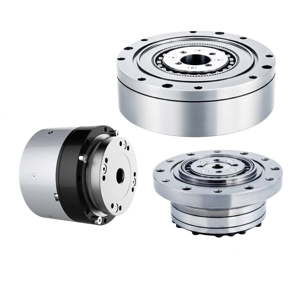
Catalog illustration of joint-module packaging. The exterior view does not establish the number, type, or safety qualification of internal sensors.
1.1 The Rotor-Side Encoder: Commutation and Velocity
A sensor before the gearhead measures motor shaft angle. In a typical encoder-based field-oriented control implementation, this supports rotor electrical-angle calculation and motor velocity feedback. Electrical frequency depends on mechanical speed and pole-pair count: f_e = pole_pairs × rpm / 60.
Request angle latency, update rate, jitter, interpolation behavior, and electrical-angle alignment procedure. Current regulation also needs current measurements; an encoder alone does not close the current loop. The PWM rate, sensor sample rate, controller execution rate, and achieved closed-loop bandwidth are separate specifications.
1.2 The Link-Side Encoder: Output Position
A sensor after the reducer measures output flange position relative to its mounting reference. This can support an outer position loop and reveal a difference between motor-derived and measured output angle. Synapticon's dual-loop documentation gives one concrete configuration: input sensing for commutation and velocity, output sensing for position, with the gear ratio configured correctly.
Check installed accuracy separately from digital resolution. As a specific product example, RLS AksIM-2 lists resolution up to 20 bits, an optional self-calibration feature, and system accuracy dependent on configuration after calibration. Those are product-family specifications, not universal limits for magnetic encoders or a guarantee for an assembled joint.
2. What a Single Motor-Side Encoder Cannot Directly Observe
2.1 Torsional Windup and Output Error
For an ideal rigid reducer, θ_link = θ_rotor / N, where N is motor revolutions per output revolution and both angles use aligned references. A real transmission adds compliance, backlash, hysteresis, and mounting error. Motor feedback alone cannot distinguish all of those from output motion.
Illustrative calculation: assume output-referred torsional stiffness of 10,000 Nm/rad and static torque of 20 Nm. The elastic twist is 20 / 10,000 = 0.002 rad, or about 0.115°. At a 0.5 m lever arm, that one angular error corresponds to about 1 mm of displacement using the small-angle approximation. These assumed inputs do not predict any catalog module. Multi-joint error also depends on pose and load direction.
A second encoder can observe transmission twist, but cannot make the reducer rigid or remove compliance beyond the sensing point. Determine whether software compensation, structural changes, external metrology, or a second encoder best addresses the actual task.
2.2 Absolute Startup Position and Homing
Single-turn absolute sensing retains a unique angle within one revolution without a battery. Multiturn tracking is needed when different permitted positions would otherwise produce the same code. An incremental encoder may require referencing if its position state is lost. An E-stop does not necessarily remove encoder power or erase a valid reference.
For a limited-travel joint with a unique single-turn output code, an absolute output encoder may avoid a physical homing sweep. For travel spanning multiple turns, ask how unpowered movement is counted and retained. A multipole or Vernier ring is not automatically a multiturn revolution counter.
Test startup in representative folded, supported, and loaded poses, including external movement while power is off. Verify the installed zero offset, reference validity checks, brake behavior, and restart authorization. Knowing the angle is only one prerequisite for a safe restart.
2.3 Transmission Faults and the Remaining Load Path
Motor/output disagreement can help detect coupling slip, transmission faults, invalid sensor frames, or lost reference. Detection depends on the fault producing a measurable residual, the allowed elastic deflection, and the monitor's timing. It is not guaranteed to identify every mechanical failure immediately.
Safe Torque Off removes motor-generated torque; it does not supply gravity support. A motor-side brake may be ineffective if a failed transmission disconnects it from the limb. Before buying a joint for a load-bearing axis, identify which mechanical parts remain in the holding path after each credible failure.
3. Mathematical Modeling: Deflection Sensing and Virtual Torque
The following diagram is an explanatory topology, not a wiring diagram or certified safety architecture. Loop labels indicate responsibilities rather than guaranteed execution rates.
Conceptual dual-loop diagram: motor feedback supports commutation and velocity; link feedback supports output position. Any safety monitor and stop response require their own validated implementation.
3.1 Governing Deflection Equations and Uncertainty
For this article, define positive transmission twist as the motor-derived output angle leading the measured link angle:
Δθ = (θ_rotor / N) - θ_link
After aligning zero offsets, signs, and timestamps, a simple quasi-static model is:
τ_est ≈ K_torsion · Δθ
Use radians for Δθ and output-referred Nm/rad for stiffness. Unwrap the motor angle before dividing by the ratio; dividing a single-turn wrapped motor code does not recover the output's absolute position. At speed, sampling skew contributes a false residual approximately proportional to velocity and time offset.
For the illustrative stiffness of 10,000 Nm/rad, an angular uncertainty of 0.0001 rad alone corresponds to 1 Nm of torque uncertainty. Stiffness uncertainty, temperature, friction, hysteresis, dynamics, and structural compliance add further error. More bits reduce quantization but do not remove those errors.
To qualify virtual torque, measure torque against an independent reference across both loading directions, operating temperature, speed, and the intended load range. Record residuals and repeatability. Do not treat a precision reducer as a pre-calibrated series-elastic torque sensor, or use this screening model as evidence for contact safety.
3.2 Non-Colocated Stability and Dual-Loop Control
Output feedback is separated from the motor by transmission compliance. Excessive gain or delay can excite flexible modes. Using motor feedback for damping and output feedback for position is one practical arrangement, but does not guarantee stability for every inertia or gearhead.
Ask the supplier for frequency-response measurements, allowed inertia range, gain settings, and acceptance tests with the intended load. A loop executing at 1 kHz does not necessarily achieve 1 kHz mechanical bandwidth. Tune filters and gains against measured resonance and delay rather than copying a catalog update rate.
RFQ handoff: before fixing the sensor option, send the supplier your travel, torque-speed envelope, output error budget, and required startup behavior through the catalog inquiry form. Request separate evidence for position accuracy, torque estimation, and safety functions.
4. Functional Safety: Evidence Beyond Encoder Count
4.1 Define the Safety Function and Required Performance
ISO 13849-1:2023 provides a design methodology for safety-related control systems; its public scope does not prescribe a required Performance Level for every application. Identify the hazards, safety functions, and required performance through the applicable risk-assessment process. The catalog record establishes scope and edition, not the compliance of a joint.
Do not infer a universal PL-c ceiling for everything sold as a single-encoder module. Likewise, “two encoders” does not automatically mean Category 3 or PL-d. Package count does not describe internal safety channels, diagnostics, or the complete safety function.
4.2 Independence and Diagnostic Evidence
Where a safety design uses motor/output comparison, request documentation of sensor and processing channels, shared supplies, clocks, communication, software, and common mechanical references. Two cores in one processor do not by themselves establish independent safety channels. Ask which faults are detected, which are excluded with justification, and which remain outside coverage.
The performance assessment must address the architecture, component reliability data, diagnostic coverage, common-cause failures, and validation of the complete function. A communication CRC detects certain data errors; it does not make ordinary position feedback safety-rated. Keep supplier certificates tied to the exact hardware, firmware, safety manual, and operating conditions.
A conceptual discrepancy threshold might include expected load deflection, sensor uncertainty, backlash, and timestamp error. A threshold wide enough to tolerate maximum twist can miss smaller faults; one that is too narrow can cause nuisance trips. Validate it against both normal operation and representative injected faults.
4.3 Stopping and Holding Need Measured Timing
There is no universal “under 2 ms detection” or “20 ms safe clamp” guarantee for this architecture. Establish a response budget from sample acquisition, filtering, fault confirmation, logic, communication where relevant, drive response, braking, and mechanical settling. Some steps overlap; assess the actual worst-case path.
Measure stopping distance and holding behavior at relevant loads, speeds, temperatures, and supply conditions. A holding brake may not be rated for dynamic stopping, and a brake command is not proof of mechanical engagement. Specify what maintains support during torque removal and after transmission failure. Confirm restart interlocks rather than automatically resuming on encoder agreement.
5. Sensor Physics: Magnetic vs. Optical vs. Inductive
This qualitative table frames supplier questions. Performance depends on the selected design, enclosure, installation, and electronics; the technology name alone does not establish an accuracy, shock rating, or price.
| Evaluation metric | Magnetic ring | Optical scale or disc | Inductive sensing |
|---|---|---|---|
| Sensing principle | Magnetic field read from a ring or target | Light reads a patterned scale | Electromagnetic coupling to a target |
| Accuracy evidence | Request installed error after calibration | Request installed scale/readhead error | Request installed target/readhead error |
| Oil, grease, and dust | Assess gap contamination and magnetic debris | Assess optical path and sealing | Assess gap contamination and sealing |
| Stray-field and electrical effects | Test under motor current and external fields | Test electronic immunity; optical sensing does not eliminate EMI | Test carrier electronics and conducted/radiated interference |
| Shock and vibration | Verify ring retention and readhead mount | Verify scale, readhead, and mount ratings | Verify target and PCB mount ratings |
| Hollow-shaft packaging | Check ring diameter, gap, and carrier | Check scale access and readhead envelope | Check target geometry and coil envelope |
| Absolute travel coverage | Confirm single-turn or actual multiturn design | Confirm coding and revolution tracking | Confirm coding and revolution tracking |
| Procurement comparison | Quote complete calibrated assembly | Quote assembly, sealing, and alignment | Quote assembly and electronics |
5.1 Runout, Calibration, and Installed Accuracy
For a simple small-eccentricity screening estimate, geometric angular error scales approximately as e / R radians. With assumed eccentricity e = 0.03 mm and pitch radius R = 40 mm, the estimate is 0.00075 rad, or about 0.043°. This is an illustrative geometric sensitivity, not a manufacturer acceptance tolerance or a complete magnetic sensing model.
Specify radial runout, axial runout, air gap, tilt, and thermal growth from the chosen encoder's installation requirements. Calibration may compensate repeatable installation error but cannot be assumed to remove load-dependent bearing motion or later assembly changes. Request the calibration method, reference uncertainty, traceability, and serial-number association; do not mandate a universal ±0.05 mm tolerance for every ring.
6. BOM Cost: An Illustrative Comparison, Not a Quote
6.1 Per-Axis Cost Model
The assumed USD values below demonstrate budgeting arithmetic only. They are not supplier prices, a market survey, or a certified safety architecture. Assume the mechanical actuator and other shared electronics are unchanged and grouped in a common base cost.
| Cost element | Single motor-side encoder | Dual encoder | Assumed difference |
|---|---|---|---|
| Common mechanical actuator and other parts | $310–$450 | $310–$450 | $0 |
| Rotor encoder | $18 | $18 | $0 |
| Output ring and readhead | $0 | $42 | +$42 |
| Drive processing and interface allocation | $12 | $22 | +$10 |
| Output sensor carrier | $0 | $6 | +$6 |
| Calibration allocation | $0 | $8 | +$8 |
| Illustrative subtotal | $340–$480 | $406–$546 | +$66 per axis |
For 30 identically configured axes, the assumed increment is 30 × $66 = $1,980. It is about 14–19% of the assumed single-encoder subtotal. Recalculate for the axes that actually need the second sensor rather than applying one configuration to the entire robot.
6.2 What the Model Excludes
Obtain quotations at the same quantity, delivery terms, and validation scope. Include tooling, minimum order quantities, test-fixture development, assembly yield, firmware work, requalification, spare parts, and calibration maintenance. Safety-qualified components and validation costs are not established by the extra $10 processing allocation.
Credit savings only when the removed function has been replaced and accepted. Virtual torque does not automatically replace a dedicated torque sensor. Absolute position does not automatically eliminate limit switches used for independent travel protection. Compare total integration cost and remaining evidence gaps, not just component count.
7. 10-Point Engineering and Sourcing RFQ Checklist
Before a sample order, ask for a written response and mark unavailable evidence as unknown:
- 1. Sensor locations: Identify motor and output measurement points, references, and any unmeasured compliance.
- 2. Startup coverage: Demonstrate unique position over permitted travel, including unpowered movement and loss of backup power where applicable.
- 3. Installed accuracy: Supply resolution, absolute error, repeatability, temperature behavior, and calibration records separately.
- 4. Interface timing: Document sample synchronization, latency, jitter, error flags, stale-data handling, and CRC behavior.
- 5. Mechanical and environmental limits: Provide gap, runout, tilt, sealing, contamination, stray-field, shock, and vibration requirements for the actual assembly.
- 6. Control tuning: State loop execution rates separately from achieved bandwidth and provide loaded stability evidence.
- 7. Torque estimation: Supply measured bidirectional stiffness curves, reference torque data, uncertainty, and valid operating range before claiming virtual-torque performance.
- 8. Safety evidence: Identify each claimed function, required/achieved performance, assessed configuration, diagnostic assumptions, and validation documents.
- 9. Stop and hold: Document fault response, brake location, dynamic-stop rating if relevant, stopping distance, and support after transmission failure.
- 10. Commercial and change control: Quote both architectures at matched volumes and define traceability, calibration ownership, firmware revisions, and requalification triggers.
8. Frequently Asked Questions
Can one output encoder handle motor commutation through a reducer?
Output angle alone generally does not uniquely describe instantaneous rotor electrical angle across a compliant, high-ratio transmission. A conventional encoder-based servo usually retains rotor sensing for commutation. Alternative observer or sensorless schemes need their own startup and operating-envelope validation; the second encoder is not a universal requirement for every motor-control design.
Is 19-bit output resolution a universal minimum for humanoids?
No. Derive the requirement from the position and torque-estimation error budgets. A 19-bit single-turn code has spacing 360° / 524,288 ≈ 0.000687°, about 2.47 arcseconds. That is quantization spacing, not installed accuracy. Noise, calibration error, compliance, and tool geometry can dominate the task result.
Why not choose optical feedback for every joint?
Choose based on installed accuracy, environment, packaging, and validated robustness. Optical feedback can be useful for precision tasks, while contamination control and alignment remain design considerations. Magnetic and inductive designs have their own interference and installation constraints. Request assembly-specific test evidence rather than a technology-wide winner.
Can dual encoders replace a torque transducer?
Sometimes an experimentally qualified deflection estimate is sufficient for the intended control task. There is no universal ±3–5% accuracy for reducer-based torque estimation. Require reference measurements and an uncertainty budget; retain independent torque sensing where the task or safety assessment needs evidence the estimate cannot supply.
Will an absolute encoder retain position when the battery is empty?
A single-turn absolute encoder reads position within one revolution without preserving a turn counter. Multiturn designs differ in how they record unpowered movement; battery-backed, energy-harvesting, or mechanically encoded implementations need model-specific checks. Also verify persistence and integrity of the joint's installed zero calibration.
Does quasi-direct drive still benefit from two encoders?
It may, for direct output position measurement, startup referencing, or a defined diagnostic function. The value of deflection sensing depends on actual stiffness and noise, not reduction ratio alone. Current-based torque estimates also depend on torque constant, current measurement, transmission losses, and dynamics. Compare both estimates against a reference within the intended operating envelope.
9. Sources and References
Sources checked November 5, 2026. Manufacturer documents support the stated configuration examples; they are not evidence of independent humanoid testing. Calculations, the decision matrix, and RFQ questions are editorial analysis with the assumptions stated above.
- ISO — ISO 13849-1:2023, Safety-related parts of control systems, Part 1. Official scope and edition. Supports the distinction between a safety design methodology and application-specific required performance; the public record does not certify a module.
- Synapticon — Dual Loop Cascaded Position Control. Official configuration documentation. Supports the example assignment of input sensing to commutation/velocity and output sensing to position. It does not establish universal control rates or safety performance.
- RLS — AksIM-2 Off-Axis Rotary Absolute Magnetic Encoder Module. Official product specifications and documentation index. Supports the named product's resolution, calibration option, and configuration-dependent accuracy. It does not establish multiturn retention, universal runout limits, or assembled-joint qualification.
10. Next Steps: Compare Evidence Before Ordering
Specify the measurement you need before choosing the sensor count. Dual feedback is valuable when transmission error must be observed, but a simpler motor-feedback joint can remain appropriate when it meets the validated task requirements.
Use the Humanoid Robot Actuator Catalog to shortlist joint classes. Then contact the engineering and procurement team with your joint map, travel, torque-speed trajectory, output error budget, and unresolved safety requirements. Ask for matched single/dual-encoder quotations and a sample-validation plan; keep missing data explicit before committing to production.
Author

Categories
Buyer path
After Reading
Use the guide to choose the next sourcing action.
Convert the guide into application-risk notes before asking for samples or controlled files.
Send prototype contextCarry accepted article checklists into sample release, pilot supply, and OEM documentation control.
Prepare OEM sample planSourcing Scope, Method, and Verification LimitsProcurement Decision Matrix: When Does the Second Encoder Help?1. Dual-Encoder Architecture: Rotor-Side vs. Link-Side Roles1.1 The Rotor-Side Encoder: Commutation and Velocity1.2 The Link-Side Encoder: Output Position2. What a Single Motor-Side Encoder Cannot Directly Observe2.1 Torsional Windup and Output Error2.2 Absolute Startup Position and Homing2.3 Transmission Faults and the Remaining Load Path3. Mathematical Modeling: Deflection Sensing and Virtual Torque3.1 Governing Deflection Equations and Uncertainty3.2 Non-Colocated Stability and Dual-Loop Control4. Functional Safety: Evidence Beyond Encoder Count4.1 Define the Safety Function and Required Performance4.2 Independence and Diagnostic Evidence4.3 Stopping and Holding Need Measured Timing5. Sensor Physics: Magnetic vs. Optical vs. Inductive5.1 Runout, Calibration, and Installed Accuracy6. BOM Cost: An Illustrative Comparison, Not a Quote6.1 Per-Axis Cost Model6.2 What the Model Excludes7. 10-Point Engineering and Sourcing RFQ Checklist8. Frequently Asked QuestionsCan one output encoder handle motor commutation through a reducer?Is 19-bit output resolution a universal minimum for humanoids?Why not choose optical feedback for every joint?Can dual encoders replace a torque transducer?Will an absolute encoder retain position when the battery is empty?Does quasi-direct drive still benefit from two encoders?9. Sources and References10. Next Steps: Compare Evidence Before Ordering
More Posts
Product Engineering
Sourcing Humanoid Robot Actuators in 2026: Overcoming Pre-Modular Bottlenecks
A 2026 procurement guide for humanoid robot actuators: qualify modules, manage pre-modular supply risk, and compare custom vs. integrated sourcing paths.

Engineering NotesProcurement Guides
Strain Wave vs. Cycloidal Reducers for Humanoid Rotary Actuators: A 2026 Sourcing & Engineering Guide
Compare strain wave vs. cycloidal reducers for humanoid rotary actuators. Check shock ratings, lost motion, sizing examples, and prepare your supplier RFQ.
Engineering NotesProcurement Guides
Axial-Flux vs. Radial-Flux Motors for Humanoid Actuators: A 2026 Sourcing Guide
Compare axial-flux vs radial-flux motors for humanoid actuators in 2026: torque density, thermal limits, tooling cost, joint fit, and RFQ sourcing checks.